
John R. Bentley 2017.
UPDATE:
Early in 2016 it seemed that the remaining work needed to finish the tugboat consisted of a finite number of manageable tasks. However for each job done it seemed that three new ones appeared! Initially I lined the inside of the metal wheelhouse with wood panelling, then on to other tasks. However much time was later spent (wasted?) on developing a rather complicated set of seven lighting circuits for the boat.
Wheelhouse doors using refrigerator style (external) hinging
(‘haven’t worked out door handles yet)
I found these old pictures:
In 1989/90 I constructed the tug’s engine, the boiler and plant were done in 1993 and the deckhouses made before the end of the last century. The keel was laid in 2000. Actually the bow and stern sections were made a couple of years prior to joining them together with the keel.
Circa 2000
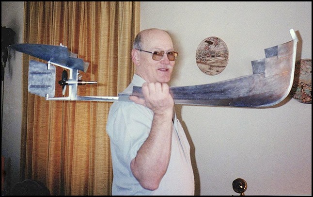
Both man and boat have gained considerable tonnage since then!
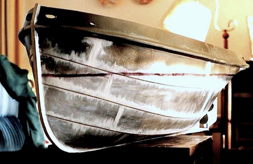
Caulking applied and ready for paint
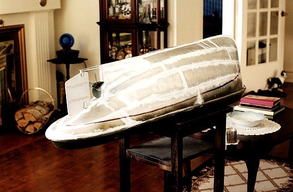
Note that the waterline is roughly parallel to the keel as on some steam tugs
There are many excellent fibreglass and wooden model boats constructed which actually look much better than a full size boat. My boat however was originally conceived only to float my then newly-built Stuart Twin Launch Engine and to resemble a typical tugboat. I used metal construction to be fireproof as the boat would contain a considerable amount of liquid fuel (kerosene). I wanted it to look as a typical workboat actually appears when about twenty years old - not as a shipbuilders’ model or a museum model.
Progress since Christmas 2016:
The boat had been in a partially constructed condition for a lot of years and I thought it might be nice to do some more work so it wouldn’t look neglected. ...Well, OK, the truth is that my wife was embarrassed every time someone came to see the boat as the old dried-up Scotch Tape let the hand railings fall off. Needless to say making permanent mountings for the railings was near the top of my list!
Please note that many of the shots which follow are mock-ups, things held in place temporarily at the time yet to be finished. Black tape was used to represent paint, window glass (all real glass) was not yet scraped or cleaned and few things were permanently screwed together. Please remember that the detail on this boat is rough, but hopefully consistent. That was my original intention – it is a metalworker’s version of a model boat, designed only to float a particular steam engine and to be viewed in operation at a distance.
Originally I had planned to mount the railings outside the deck with special holders for the stanchions riveted to the outside edge of the deck. With much more information available to me now from the internet I searched hundreds of tug pictures of every vintage and only found a single example of rails being secured in this fashion. All the others are done much like a land-based house deck – the stanchions are mounted on the deck surface near the edge.
Moving them inside to the deck surface was deemed "impossible" because all four of the stainless steel main railing sections were already silver brazed to form the exact shape to fit in the outside position on the deck. However in a moment of unjustified confidence I decided to cut the aft railings at the back corners corners and shorten them in both directions to allow them to fit in the new position. The forward two railings were more of a problem as they are curved to go around the wheelhouse and must meet the ladder rails properly. Through some fluke of luck the entire job was completed without problem. I drilled the twenty holes in the metal deck and the stanchions can be pushed down into the holes to the proper depth. When installed, they look much better than the temporary Scotch Tape job.
Test fitting forward railings during silver brazing
The upper metal deck has been covered with a heavy sanding cloth of fairly fine grit. I had two sheets which I bought for the purpose many years ago. I am a bit worried about the weight however as that deck is quite high on the boat and weight will not help stability. I have already added an extra mast and a rubber-covered false floor/riser in the wheelhouse – these things all add to the weight, bringing the metacentre higher above the centre of buoyancy. There are now two cowl ventilators and a lifeboat to add, so I am being cautious. My plan is to cast some lead bars to fit very low in the bilge – hopefully that will make a big difference. Unlike a wooden model, this all-metal boat can and will sink to the bottom if it lists too far and takes on water.
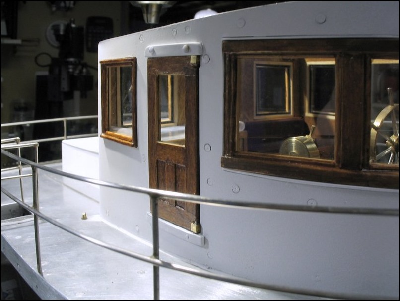
I used the same paint on the wheelhouse as I used on the lower deckhouse about twenty years ago. The old white has taken on very nice appearance over that time but the fresh paint looks a bit too “milk of magnesia”. Possibly it can be aged somewhat after it toughens up by buffing it with a not-too-pristine rag. The doors and windows are typical of marine types used in the pre-1950’s. Of course unlike land-based woodwork, mitre joints in the trim were considered a definite no-no by better boatbuilders due to the extreme humidity conditions at sea.
I am pleased with the overall appearance of the finish after looking over many hundreds of workboats of all ages on the web. As a child I spent quite a bit of time in and around small boats on the waterfront and of course formed early impressions from our old car ferries including making many observations on the steamships Charles A. Dunning and S.S. Prince Edward Island.
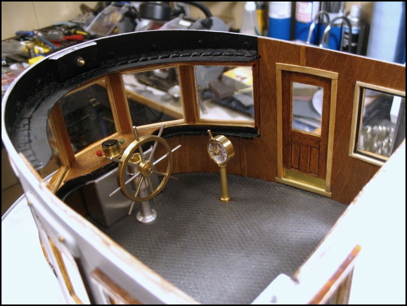
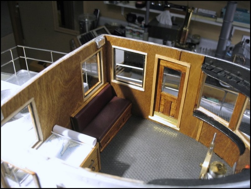
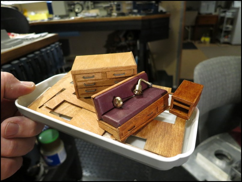
The chart table is visible through the port wheelhouse door
it is “rough-and-ready” tugboat furniture!

The tools that can be seen through the window are the full size ones in a cabinet in my workshop
The chart is under a real sheet of glass and depicts Hillsborough Bay just outside Charlottetown Harbour in Canada
It includes all depth markings and a compass rose - it is held under glass as common in full size practice.
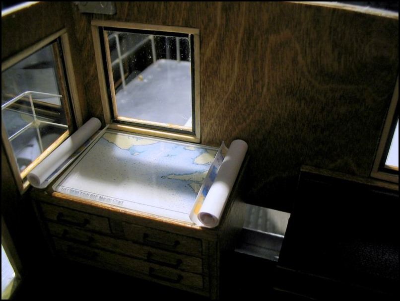
The rolled-up charts at the sides are also complete and accurate – both show the eastern portion of the Northumberland Strait
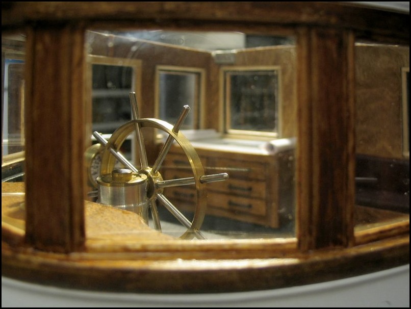
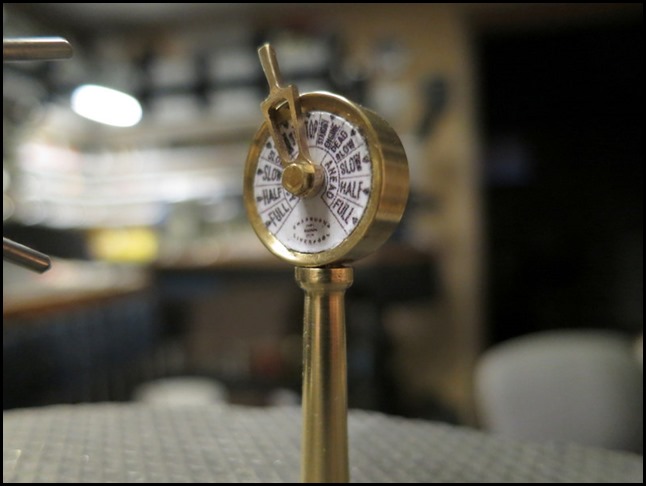
Dirty windows, but this shows the back side of the wheel
Through the door you can see the wheel and the Chadburn engine telegraph
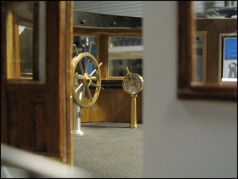
The telegraph dial was reduced in size from a picture of an original blueprint of the dial used on the Lusitania
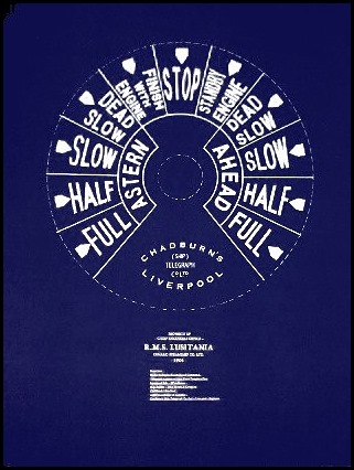
Lusi's telegraphs used white lettering-on-dark, but I chose to print it with a white background - common on many smaller boats
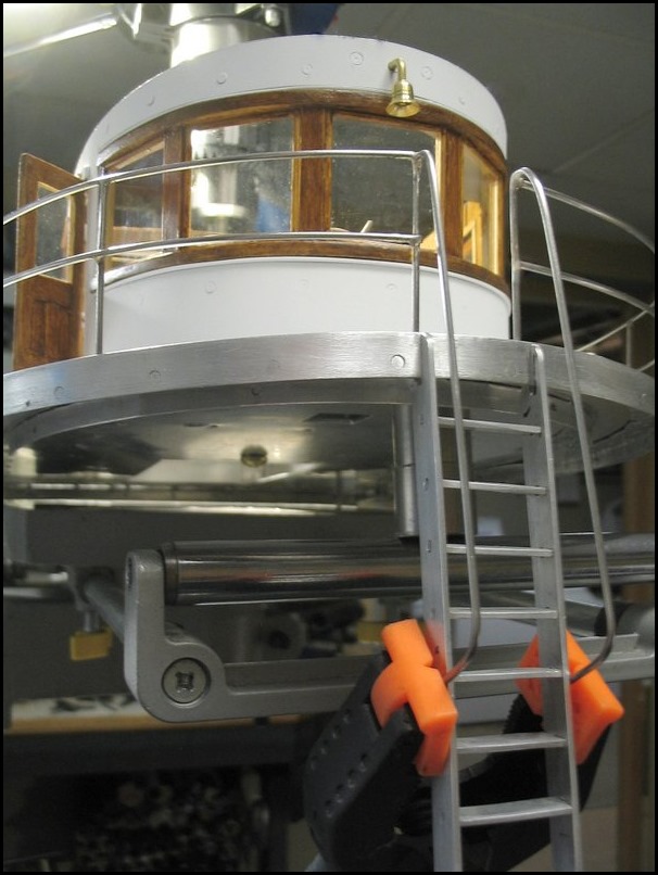
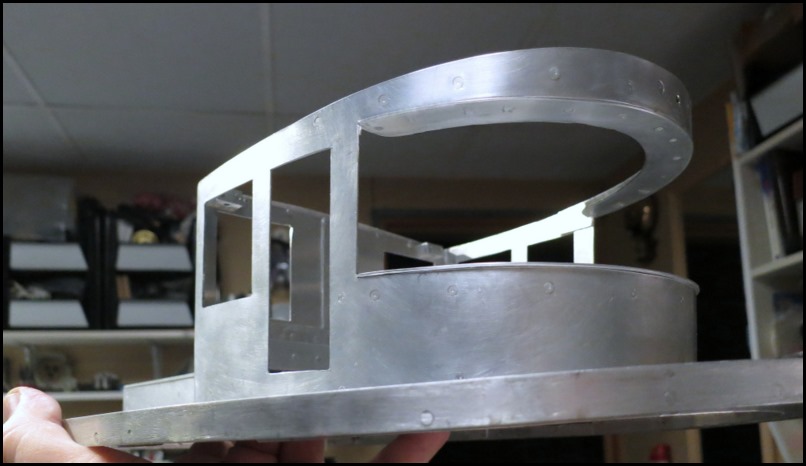
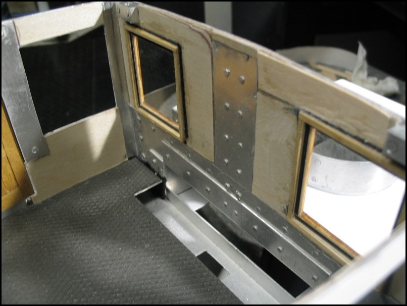
Here is the wheelhouse deck in my "shipyard"
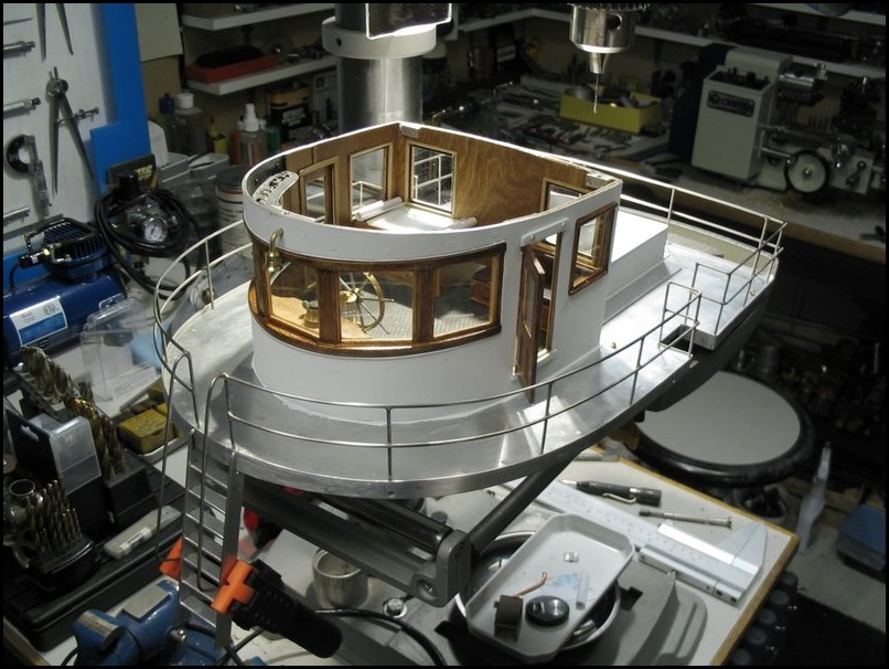
A brass kick plate and door sill can be seen in this shot
Of course the non-scale black bit at the top is not visible with the roof attached due to the sight lines
The entire interior is barely visible when the roof is on. I have tried using a flashlight and it still doesn’t look like much. White LEDs look great on their own or against light coloured surfaces but the wood doesn’t reflect that type of light and so the LEDs do little to show what is inside. I guess I’m ok with that – it was only a month’s work. At least if someone actually peers directly in a window they will see that something is there other than the rough end of rivets and lapped platework. I should add curved steam radiators at the front, a speaking tube, whistle handle and a pilot’s stool, but my limited time is better spent doing more important parts of this project.
I did add ten deck lights around outside of the lower deckhouse which (after being suitably dimmed) look very good judging from visitors' reactions. In addition there are ceiling lights on the inside - galley, berths, etc. I would like to add one to the head and a few in the engine room.
There are electrical panels, functioning conduits and other things to go on the back wall
The seat is real leather of course:-)

The material was from a winter overcoat that I bought in the 1980’s. It was not a cheap coat - it had the softest leather I ever felt and I loved it...however the dye was not fast and it irreparably stained many of my shirt collars. I always had to wear a dark scarf for protection and eventually I cut up the coat. Since that time, for revenge I have used the scraps for every model project requiring leather.
Rewind back to the end of January 2016 for a moment...
A little bit of that same white paint

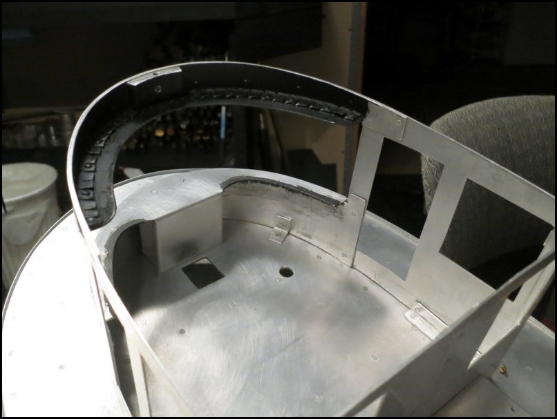
I painted out the ugly curved window header in flat black to eliminate any odd reflections on the ceiling
A tug’s strong sheer line puts the wheelhouse deck at quite an upward angle -
A false floor or a riser for the helm are two common solutions (in real life as well)
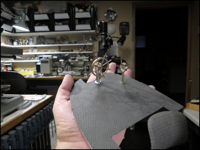
This aluminum floor is crowned and covered with pure uncured rubber.
I allowed some weeks’ worth of fine sawdust (acquired during the woodworking) to stick into the uncured surface to create a non-pristine appearance. It surely beats that super shiny “1960’s glossy galoshes look” ...Oh yeah, I still wear those things in the winter – I must be the only one in town who still does judging by the comments I get:)
These two access holes were cut in the wheelhouse deck underneath the false floor so that the wheel and telegraph could be removed for maintenance
This seemed enough padding as a heavy layer of epoxy glue would follow before the plywood

Different layers of sheet metal required some filling to make a level surface for the attachment of the 1/32” birch plywood panelling
These wheelhouse front windows were made years ago but not stained, varnished or affixed to the cabin

The aforementioned plywood sheathing stained and covered in satin polyurethane
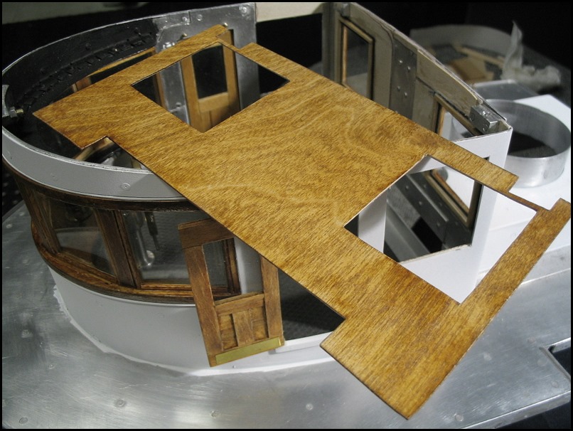
Yes, the grain is a bit coarse for 1:24 scale. However, much like stage props used in live theatres, a little exaggeration sometimes looks more real than perfect scale. I am trying to leave the impression of a well-used workboat - not a pristine private yacht or cruise ship.
The wood used was mainly birch and the stain was Maxwell House instant coffee (Original Roast)
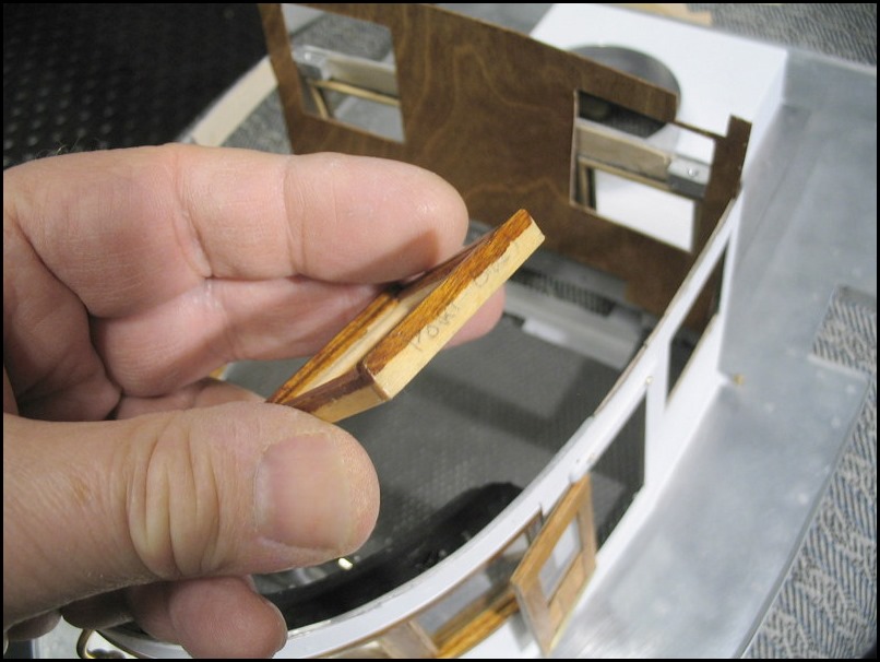
Making furniture with off-centre concave bottoms to suit the crown of a deck is not my forté but I tried...
The little book stand/end table was designed to go flat against the side of the chart table and against the end of the bench seat, hence the rails on the front and right side only. In the end, the thickness of the walls increased above expectations and the little table no longer fits the space. Its real purpose was to hide the hole where the electrical conduits come up from below carrying 12 conductors for lighting circuits. The hole cannot be seen with the roof on, so I have lost interest in filling it in at the moment. I’ll see how I feel about that when the wiring is done.
Testing the masthead lights
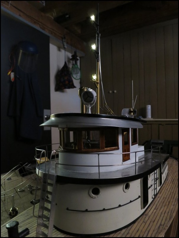
(the main mast’s front stay and the shrouds as well as the upper railing were all absent during this mock-up)
Fortunately I have left woodworking for a while and completed lanterns for the steaming and navigation lights and installing the cabin lights. The deck lights have been installed and soon I will be able to wire up the whole mess.
I decided to add an aft mast to support the stern light and the towing light. The new mast, like the main mast is made up from silver brazed stainless steel.
The new aft mast with two 135-degree lamps (turned off in this shot)
- white stern light (lower) and yellow towing light (upper)

This is an old picture
Obviously missing in the above photo are the deck covering, the lifeboat (below the aft mast), two cowl ventilators (both sides of stack), life rings and the portholes for the engine room skylight. The bare metal decks are now covered, the railings painted and the front sun visor has been cut down to final size and painted flat black and green underneath.
This is a newer photo showing most of those changes
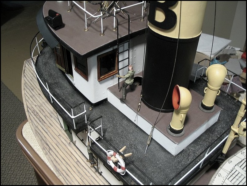
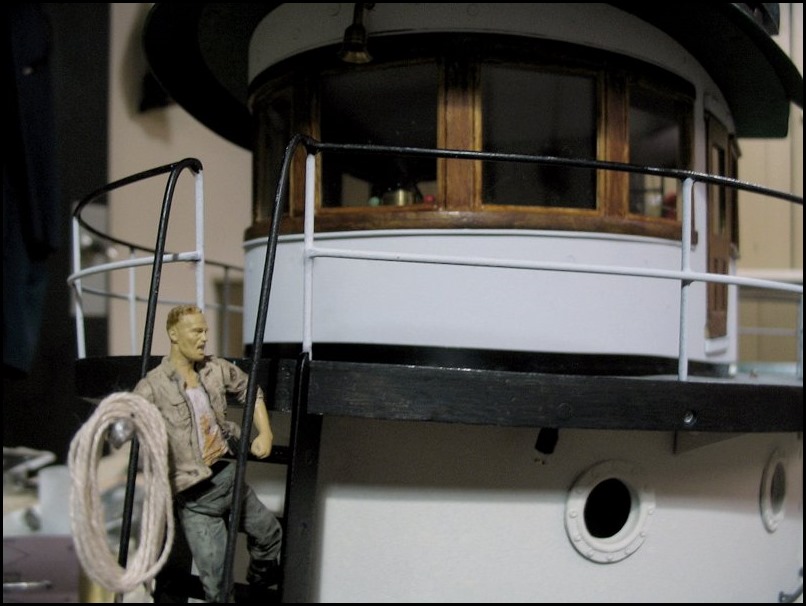
Experimenting with a figure from the television program “The Walking Dead”
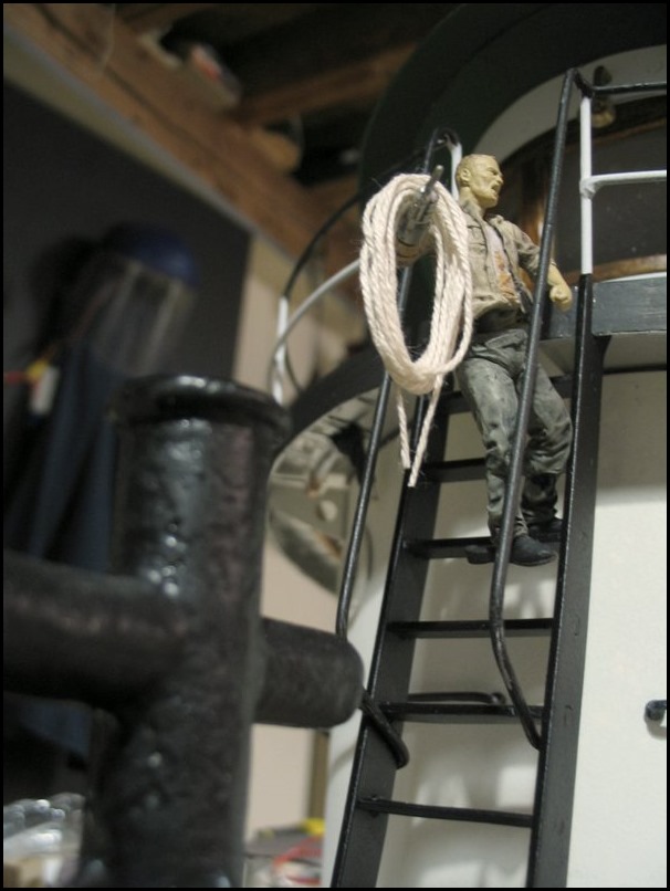
The tug’s weathered fore bitts are showing in the foreground
I originally thought that I would wrap this boat job up in a couple of weeks (!!!) and continue on with my land-based packaged watertube boiler project. That was not to be.
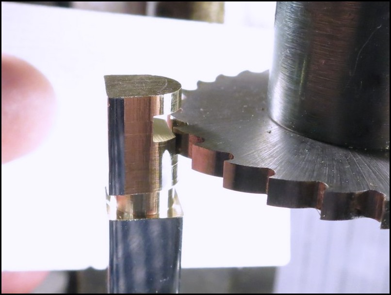
I still needed seven navigation lamps: three 225-degree white mast head lamps, two 112.5-degree red and green side lights, a 135-degree white stern light and a 135-degree yellow towing light. They were all made by essentially the same method. The 112.5-degree side lights were more difficult because the stock had to be located off-centre in the chuck.
Three general shapes of navigation lamps are typical – viewing from the top they can be D-shaped, round or a quarter circle (to fit in right angle screens on side lights). All three types have been around for at least a hundred years and still being made.
Milling a lantern from square chrome plated brass using the rotary table
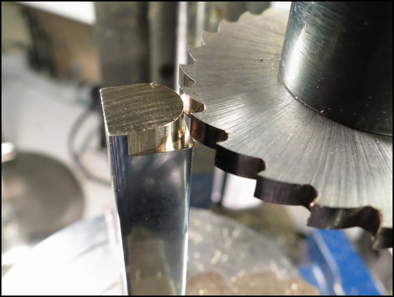
(called steaming lights in earlier times)
Cutting the notch for the light to get out at the proper dispersion angle
One of the 225-degree mast head navigation lights on the main mast
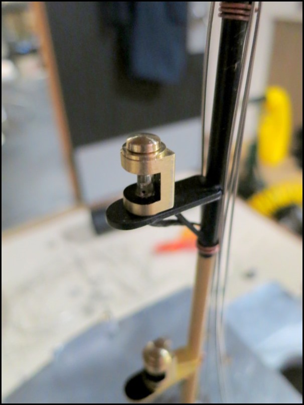
The top two lamps (including this one) will be painted black and the lower one painted buff on this mast
Remote control
A change being as good as a rest, I decided that after twenty-seven years it was time to finally select a remote control system. I had purposely held off, knowing that things in electronic technology were advancing at an exponential rate. An early purchase in the 1990’s or 2000’s would have been woefully outdated before the ship was ready to sail. My strategy was sound and I am overjoyed at the capabilities and ridiculously low cost of the latest control systems. However it has been so much fun simply playing with the remote control equipment that I spent the summer and autumn of 2016 testing and experimenting. I acquired two identical ten-channel transmitters (one for spare) and five receivers. Receivers are inexpensive and I considered that some simpler boat models might be in my future so I wished to avoid the possibility of future compatibility problems.
The only sad note is that there appears to be nothing made at this date which is specifically designed for model ships. The industry targets model airplanes, drones, quadcopters and to a lesser degree, helicopters and model racing cars. Apparently none of these require reverse thrust, something very important in model ships as it provides for braking and maneuvering - however adaptation for boats is reasonably easy. The much more stringent control requirements of flying machines has resulted in excellent quality radio systems available at reasonable cost which have a very high degree of precision and reliability.
Telemetry
Many years ago I was hoping to devise some sort of telemetry system to receive information back from the tugboat’s steam plant. It seemed almost a dream at that time but now even systems costing between fifty and a hundred dollars can be expected to have telemetry. I have the capability of up to fifteen telemetering channels – I acquired seven sensors to date. I bought a multi function lighting control module and have amassed eighteen servos to date.
This is too much technical talk but I have to say much credit is due to our software friends around the world for their tremendous contributions to the RC hobby. I really can’t understate the degree to which RC equipment has advanced – even in the last couple of years.
Steering by remote
Most recently I devised a decent steering system with rudder quadrant to allow slow realistic steering of the boat instead of the violent “flicking” turns which are characteristic of using instant-response aeroplane servos in a model boat with a large rudder.
To complement the extra gear reduction added to the rudder I plan to add a ship's wheel to the RC transmitter which will move the existing joystick through an appropriate reduction. This will be a simple snap-on addition to the front of the box. The overall result will require turning the wheel through a few full turns to move the rudder hard to port or starboard. Hopefully this will give much more realistic turns and provide finer control when following a straight course.
In the picture below the large threaded hole is in a bracket firmly attached to the hull.
A bolt (with a head disguised as a deck cleat) is used to affix the deck and superstructure assembly at the stern
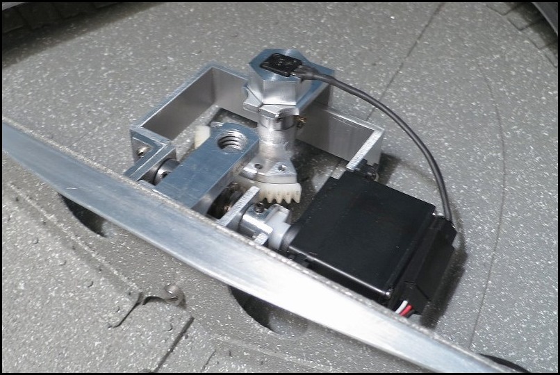
The UHMW polyethylene servo coupling piece (in the lower part of the picture driving the worm)
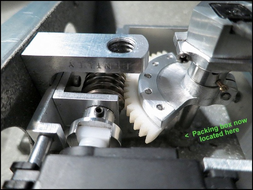
note: this is an earlier picture taken before the brass packing box was installed.
The brass packing box for the rudder stock is visible in this view
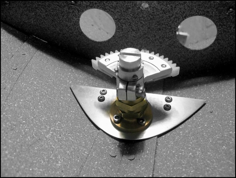
The completed steering gear with the servo's position sensor on top and the modified servo to the right
That is all for now. I could go on at great length about a supply of low cost excellent LEDs which are most suitable for model ships. I have about twenty-five in use in the tug at the moment and expect to add another five or so. I can run all of these lights for hours with one 25-cent-piece-sized CR2032 battery. The quality control, color and miniscule current requirements of these LEDs are amazing. Anyway, that is a topic for another page, another day!
Back to Page One of the Tugboat
Tugboat Engine Room page
or
Back to the ModelEngines.info Site Home Page